找回密码
 立即注册
搜索
查看: 37|回复: 2

路由与交换基础期末复习2023

[复制链接]

9

主题

4

回帖

105

积分

管理员

积分
105
发表于 2023-6-17 00:16:03 | 显示全部楼层 |阅读模式 来自 广东深圳
拓扑图:


拓扑及题目下载:


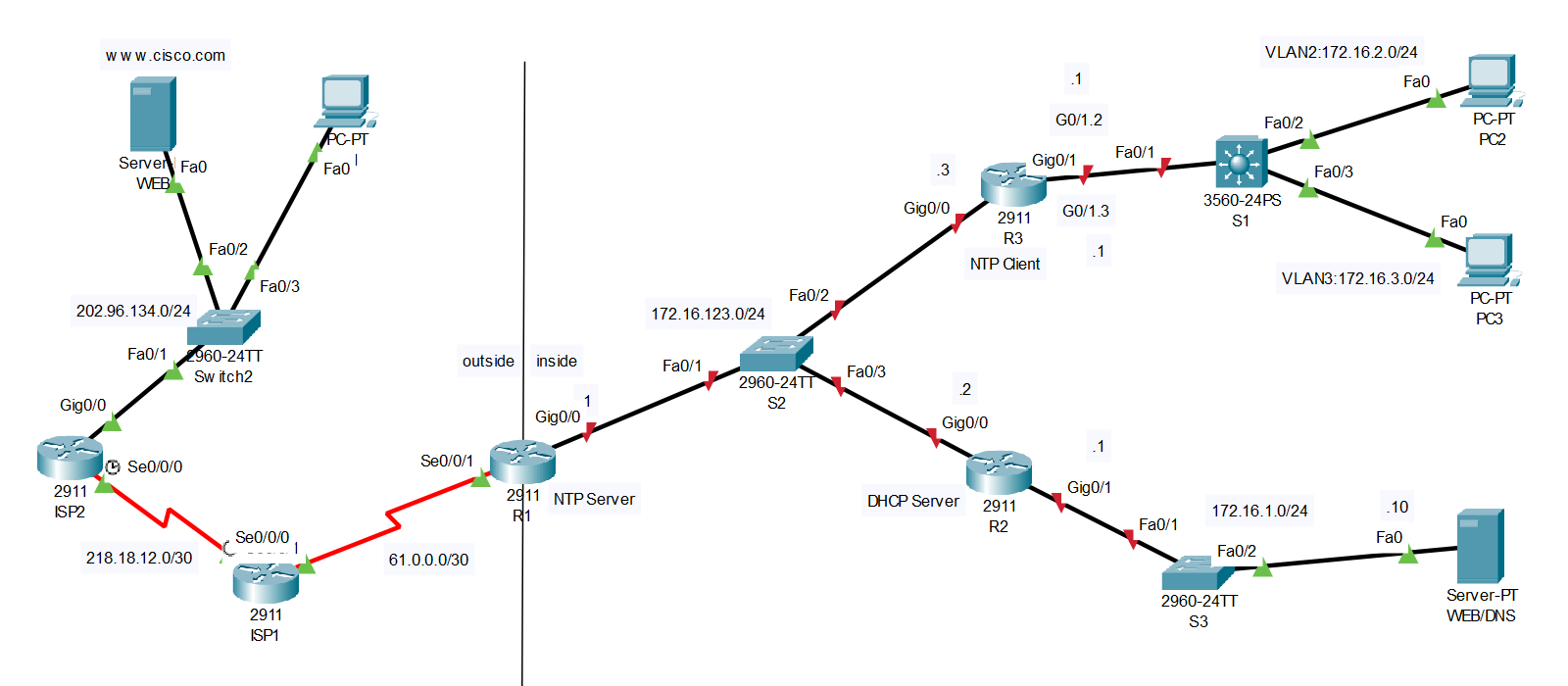
注意:外部的路由器ISP、服务器WEB和PC1全部配置好,不需要做任何配置。
R1的S0/0/1接口IP地址已经配置好,不要做更改,G0/0需要配置IP地址。

1.基本配置(配置交换机S3)
(1)主机名为S3
命令格式:
修改主机名
hostname 主机名
  1. Switch>en
  2. Switch#conf t
  3. Enter configuration commands, one per line.  End with CNTL/Z.
  4. Switch(config)#hostname S3
  5. S3(config)#
复制代码


(2)配置enable secret密码为cisco,配置控制台密码为cisco,配置telnet密码为cisco,登录后的权限级别为15级。
命令格式:
修改特权模式密码
enable secret 密码
线路模式下:
修改登录密码
password 密码
登录后权限级别
privilege level 权限级别


  1. S3(config)#enable secret cisco
  2. S3(config)#line console 0
  3. S3(config-line)#password cisco
  4. S3(config-line)#login
  5. S3(config-line)#privilege level 15
  6. S3(config-line)#exit
  7. S3(config)#line vty 0 4
  8. S3(config-line)#password cisco
  9. S3(config-line)#login
  10. S3(config-line)#privilege level 15
  11. S3(config-line)#exit
  12. S3(config)#
复制代码


(3)为了安全起见,请将密码加密。


  1. S3(config)#service password-encryption
复制代码


(4)配置管理IP地址为172.16.1.2,掩码为24位,网关为172.16.1.1


  1. S3(config)#interface vlan 1
  2. S3(config-if)#ip address 172.16.1.2 255.255.255.0
  3. S3(config-if)#no shutdown
  4. S3(config-if)#exit
  5. S3(config)#ip default-gateway 172.16.1.1
复制代码


(5)配置服务器(内部)的IP地址为172.16.1.10,掩码为24位,网关为172.16.1.1


2.交换部分
(1)在交换机S1上创建VLAN信息如下:


VLAN IDVLAN名称接口划分对应子网对应路由器子接口
2VLAN2S1:F0/2172.16.2.0/24R3:G0/1.2:172.16.2.1
3VLAN3S1:F0/3172.16.3.0/24R3:G0/1.3:172.16.3.1


命令格式:
创建VLAN
vlan VLAN编号
VLAN命名(VLAN配置模式下)
vlan VLAN名称
接口模式
switchport mode 接口模式(access|trunk|dynamic)
划分接口至VLAN
switchport access vlan VLAN ID

  1. S1>en
  2. S1#conf t
  3. Enter configuration commands, one per line.  End with CNTL/Z.
  4. S1(config)#vlan 2
  5. S1(config-vlan)#name VLAN2
  6. S1(config-vlan)#exit
  7. S1(config)#vlan 3
  8. S1(config-vlan)#name VLAN3
  9. S1(config-vlan)#exit
  10. S1(config)#interface f0/2
  11. S1(config-if)#switchport mode access
  12. S1(config-if)#switchport access vlan 2
  13. S1(config-if)#exit
  14. S1(config)#interface f0/3
  15. S1(config-if)#switchport mode access
  16. S1(config-if)#switchport access vlan 3
  17. S1(config-if)#exit
  18. S1(config)#
复制代码


命令格式:
配置以太网子接口vlan号,封装格式为802.1q
encapsulation dot1Q VLAN编号


  1. R3>en
  2. R3#conf t
  3. Enter configuration commands, one per line.  End with CNTL/Z.
  4. R3(config)#interface g0/1
  5. R3(config-if)#no shutdown
  6. R3(config-if)#exit
  7. R3(config)#int g0/1.2
  8. R3(config-subif)#encapsulation dot1Q 2
  9. R3(config-subif)#ip address 172.16.2.1 255.255.255.0
  10. R3(config-subif)#no shutdown
  11. R3(config-subif)#exit
  12. R3(config)#interface g0/1.3
  13. R3(config-subif)#encapsulation dot1Q 3
  14. R3(config-subif)#ip address 172.16.3.1 255.255.255.0
  15. R3(config-subif)#no shutdown
  16. R3(config-subif)#exit
  17. R3(config)#
复制代码


3.路由部分
(1)配置默认路由:在路由器R1上配置默认路由,出接口为S0/0/1


  1. R1>en
  2. R1#conf t
  3. R1(config)#ip route 0.0.0.0 0.0.0.0 s0/0/1
复制代码


(2)配置RIPv2路由:
- 路由器R1(外网接口不能宣告),R2和R3之间运行RIPv2路由协议,
- 关闭自动汇总,
- 将不必要的接口(接PC的接口)配置为被动接口,
- 在R1,向RIP网络注入一条默认路由。


  1. R1(config)#interface g0/0
  2. R1(config-if)#ip address 172.16.123.1 255.255.255.0
  3. R1(config-if)#no shutdown
  4. R1(config-if)#exit
  5. R1(config)#router rip
  6. R1(config-router)#version 2
  7. R1(config-router)#no auto-summary
  8. R1(config-router)#network 172.16.0.0
  9. R1(config-router)#default-information originate
  10. R1(config-router)#exit
  11. R1(config)#
复制代码

  1. R2>en
  2. R2#conf t
  3. Enter configuration commands, one per line.  End with CNTL/Z.
  4. R2(config)#interface g0/0
  5. R2(config-if)#ip address 172.16.123.2 255.255.255.0
  6. R2(config-if)#no shutdown
  7. R2(config-if)#exit
  8. R2(config)#interface g0/1
  9. R2(config-if)#ip address 172.16.1.1 255.255.255.0
  10. R2(config-if)#no shutdown
  11. R2(config-if)#exit
  12. R2(config)#router rip
  13. R2(config-router)#version 2
  14. R2(config-router)#no auto-summary
  15. R2(config-router)#passive-interface g0/1
  16. R2(config-router)#network 172.16.0.0
  17. R2(config-router)#exit
  18. R2(config)#
复制代码

  1. R3>en
  2. R3#conf t
  3. Enter configuration commands, one per line.  End with CNTL/Z.
  4. R3(config)#interface g0/0
  5. R3(config-if)#ip address 172.16.123.3 255.255.255.0
  6. R3(config-if)#no shutdown
  7. R3(config-if)#exit
  8. R3(config)#router rip
  9. R3(config-router)#version 2
  10. R3(config-router)#no auto-summary
  11. R3(config-router)#passive-interface g0/1
  12. R3(config-router)#network 172.16.0.0
  13. R3(config-router)#exit
  14. R3(config)#
复制代码


(3)配置VLAN间路由
在路由器R3上配置VLAN2和VLAN3的路由,创建子接口G0/0.2(172.16.2.1/24,对应VLAN2)和G0/0.3(172.16.3.1/24,对应VLAN3),注意交换机S1的F0/1接口配置为trunk模式。


  1. S1(config)#interface f0/1
  2. S1(config-if)#switchport trunk encapsulation dot1q
  3. S1(config-if)#switchport mode trunk
  4. S1(config-if)#exit
复制代码


4.配置DHCP
在路由器R2上,创建两个地址池,按照下表完成。


地址池名称网段和掩码网关DNS Server排除地址
VLAN2172.16.2.0/24172.16.2.1172.16.1.10172.16.2.1-172.16.2.50
VLAN3172.16.3.0/24172.16.3.1172.16.1.10172.16.3.1


命令格式:
配置DHCP排除地址
ip dhcp excluded-address 低位地址 高位地址(可选)
创建DHCP池
ip dhcp pool 地址池名称
配置DHCP池网段和掩码(DHCP模式下)
network 网段 掩码
配置DHCP默认网关(DHCP模式下)
default-router 网关地址
配置DNS服务器(DHCP模式下)
dns-server DNS服务器地址

  1. R2(config)#ip dhcp excluded-address 172.16.2.1 172.16.2.50
  2. R2(config)#ip dhcp excluded-address 172.16.3.1
  3. R2(config)#ip dhcp pool VLAN2
  4. R2(dhcp-config)#network 172.16.2.0 255.255.255.0
  5. R2(dhcp-config)#default-router 172.16.2.1
  6. R2(dhcp-config)#dns-server 172.16.1.10
  7. R2(dhcp-config)#exit
  8. R2(config)#ip dhcp pool VLAN3
  9. R2(dhcp-config)#network 172.16.3.0 255.255.255.0
  10. R2(dhcp-config)#default-router 172.16.3.1
  11. R2(dhcp-config)#dns-server 172.16.1.10
  12. R2(dhcp-config)#exit
  13. R2(config)#
复制代码


在路由器R3的子接口下配置DHCP中继,完成后,PC2和PC3可以通过DHCP方式获得IP地址。

命令格式:
配置DHCP中继(接口模式下)
ip helper-address DHCP服务器地址


  1. R3(config)#interface g0/1.2
  2. R3(config-subif)#ip helper-address 172.16.123.2
  3. R3(config-subif)#exit
  4. R3(config)#interface g0/1.3
  5. R3(config-subif)#ip helper-address 172.16.123.2
  6. R3(config-subif)#exit
  7. R3(config)#
复制代码


5.在路由器R1上配置NAT:
(1)配置端口映射,使得外网主机可以访问内网服务器的WEB服务,地址对应关系:(内部IP地址:172.16.1.10,端口号:80)/ (外部IP地址:61.0.0.2,端口号:80)。

命令格式:
配置端口映射
ip nat inside source static tcp 内部地址 端口号(内部) 外部地址 端口号(外部)

  1. R1(config)#ip nat inside source static tcp 172.16.1.10 80 61.0.0.2 80
复制代码


(2)配置PAT,使得内网用户(使用标准ACL,标号为1,允许网段172.16.0.0/16)可以访问外网,直接使用接口S0/0/1作为地址复用(过载)。
配置ACL
access-list 标号 permit(允许)|deny(拒绝) 网段 反掩码

  1. R1(config)#access-list 1 permit 172.16.0.0 0.0.255.255
  2. R1(config)#ip nat inside source list 1 interface s0/0/1 overload
  3. R1(config)#interface g0/0
  4. R1(config-if)#ip nat inside
  5. R1(config-if)#exit
  6. R1(config)#interface s0/0/1
  7. R1(config-if)#ip nat outside
  8. R1(config-if)#exit
  9. R1(config)#
复制代码

6.配置NTP(KEY ID 1,密码:cisco)

请看本贴3楼。


7.配置ACL
在R2上配置扩展ACL,
(1)拒绝172.16.2.0/24访问服务器(172.16.1.10)的WEB服务。
命令格式:
ip access-list standard(普通)|extended(拓展) ACL名称|ACL编号


  1. R2(config)#ip access-list extended ACL2
  2. R2(config-ext-nacl)#deny tcp 172.16.2.0 0.0.0.255 host 172.16.1.10 eq 80
  3. R2(config-ext-nacl)#permit ip any any
  4. R2(config-ext-nacl)#exit
  5. R2(config)#interface g0/0
  6. R2(config-if)#ip access-group ACL2 in
  7. R2(config-if)#exit
  8. R2(config)#
复制代码


本帖子中包含更多资源

您需要 登录 才可以下载或查看,没有账号?立即注册

×
站长提醒
请您在发表言论时,遵守当地法律法规。

9

主题

4

回帖

105

积分

管理员

积分
105
 楼主| 发表于 2023-6-17 17:19:52 | 显示全部楼层 来自 广东深圳
8.测试
按照题目要求完成截图。
查看PC2的IP地址
C:\>ipconfig /all


查看PC3的IP地址
C:\>ipconfig /all


使用PC3,telnet S3
C:\>telnet 172.16.1.2


查看S1的vlan
S1#show vlan brief


在PC2(内部的PC),使用浏览器访问www.cisco.com
http://www.cisco.com


在PC2(内部的PC),使用浏览器访问172.16.1.10
http://172.16.1.10


在PC3(内部的PC),使用浏览器访问172.16.1.10
http://172.16.1.10


在PC1(外部的PC)上使用浏览器访问61.0.0.2
http://61.0.0.2


查看R3的路由表
R3#show ip route


查看R3的NTP状态
R3#show ntp status


查看R3的时钟
R3#show clock


9

主题

4

回帖

105

积分

管理员

积分
105
 楼主| 发表于 2023-6-19 09:21:26 | 显示全部楼层 来自 广东深圳
6.配置NTP(KEY ID 1,密码:cisco)
(1)在R1,配置NTP服务器,手工修改时间,时间为考试当天。
命令格式:
配置时间
clock set 时时:分分:秒秒 日期 月份 年份
配置NTP验证密码
ntp authentication-key KEY ID md5 密码
配置NTP信任密钥
ntp trusted-key KEY ID

  1. R1#clock set 16:00:00 17 june 2023
  2. R1#conf t
  3. Enter configuration commands, one per line.  End with CNTL/Z.
  4. R1(config)#ntp master
  5. R1(config)#ntp authentication-key 1 md5 cisco
  6. R1config)#ntp authenticate
  7. R1(config)#ntp trusted-key 1
  8. R1(config)#
复制代码

(2)在R3,配置NTP客户端,自动同步时间。


  1. R3(config)#ntp server 172.16.123.1 key 1
  2. R3(config)#ntp authentication-key 1 md5 cisco
  3. R3(config)#ntp trusted-key 1
  4. R3(config)#ntp authenticate
  5. R3(config)#
复制代码


您需要登录后才可以回帖 登录 | 立即注册

本版积分规则

Archiver|手机版|小黑屋|爱学习

GMT+8, 2025-12-16 05:27 , Processed in 0.023719 second(s), 21 queries .

Powered by Discuz!

Copyright ©2023 红旗在飘扬 , All Rights Reserved.

快速回复 返回顶部 返回列表